Sharp PC-4600 (PC-4602/PC-4641) Expansion Bus ISA Breakout

This project provides two 8-bit ISA Slots to the Sharp PC-4600 (PC-4602/PC-4641) laptop computer systems.
Introduction
Following on from the External Floppy Drive project, this time looking at more external expansion using the EXPBUS connector on the rear of the system.
To my knowledge this is the first ever product created to plug into the EXPBUS interface on the Sharp PC-46xx series. I am unable to find any official documentation around a product that was released (If you know of any, please let me know). There are some documents for the Sharp PC-7000, where an expansion unit was sold (Product code CE-700E, CE-710E and CE-700D), however this was a 16-bit interface and not likely compatible.
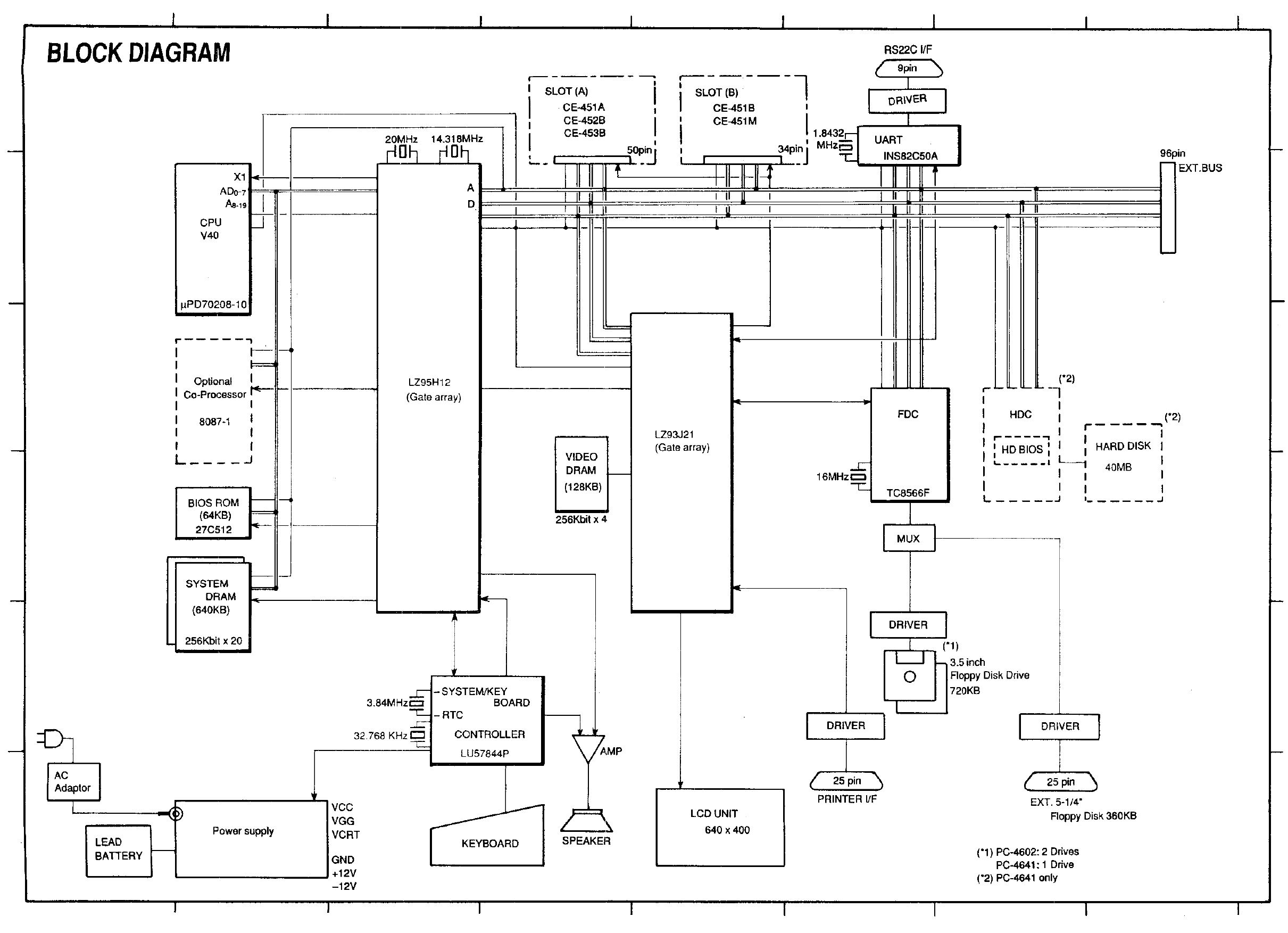
This system is an NEC V40 based system and is 8-bit. There are a couple of custom clots internally for ROM Cards and the CGA Video card options.
Other than the serial port, parallel port and the external floppy interface, there are no other ways to expand the system. We are so spoilt with USB these days.
 TIP: Click on Image to open larger
System Detail
The EXT.BUS or EXPBUS connector (depending on the schematic and service manual page you look at), is located on the rear of the system. This makes it much easier to integrate with than the bottom of more modern 386-Pentium era systems.
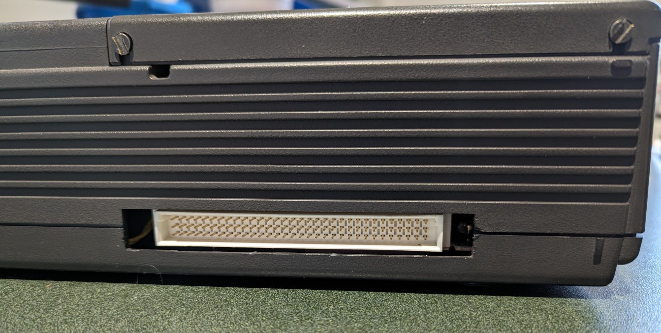
This connector may be covered by a piece of plastic that needs to be cut away before installing this expansion.
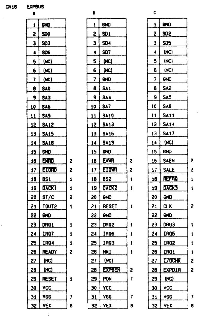
The connector provides the standard ISA Bus signals, including power in and out for the system (with some limitations), effectively providing docking station capabilities to the system if desired.
The expbus connector doesn’t appear to follow any other standards. PC104 was common around this time, but the pinout does not resemble this in any way.
When plugging in to this connector, it doesn’t disable or change any internal options, it is a simple additional port.
This is the full pinout of the connector as shown in the service manual.
PCB Design
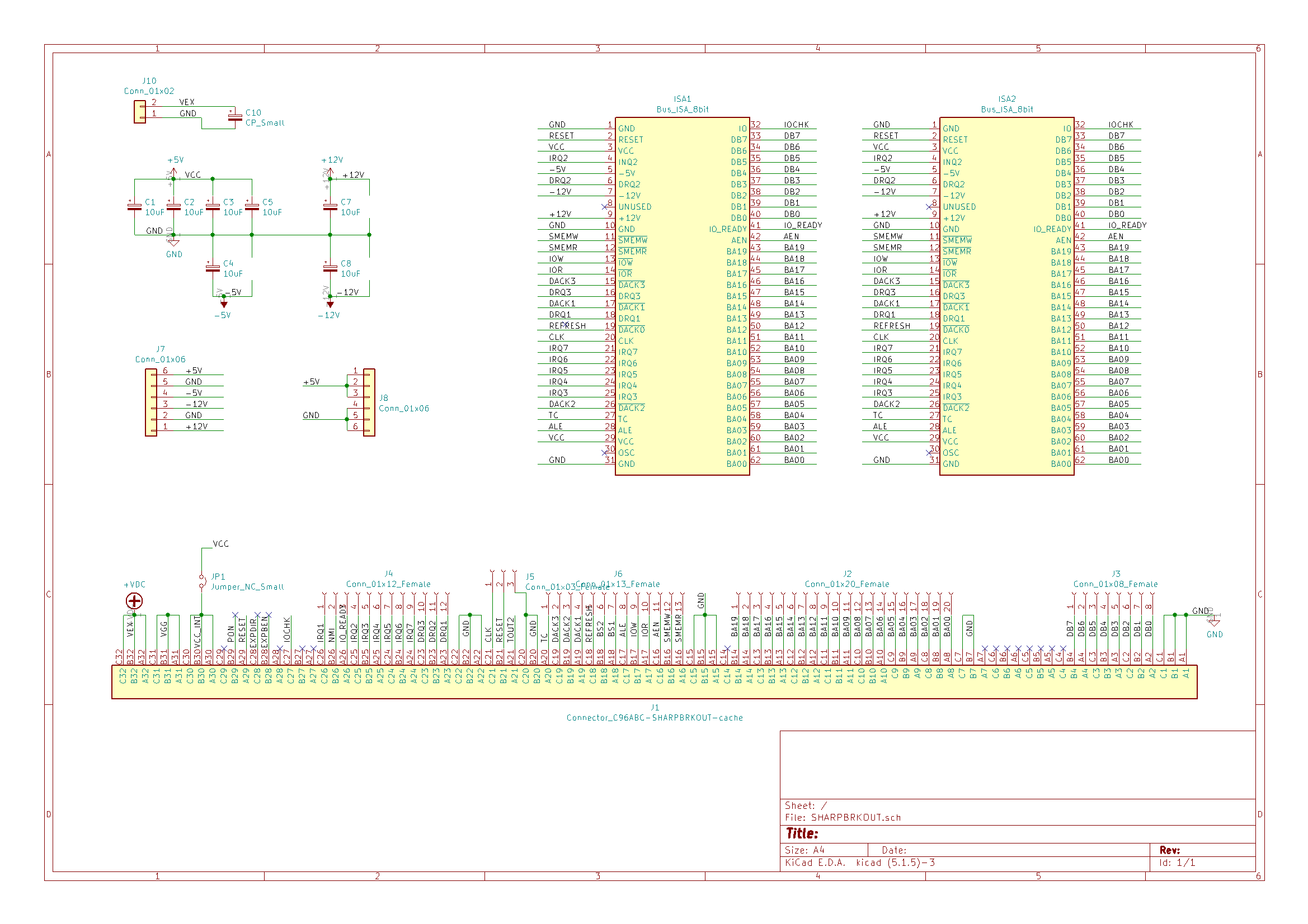
Once the Expansion bus connector pinout and signals are understood, it is a matter of mapping the connector to the ISA Bus edge connectors, and provide some essential filtering capacitors, however the design is entirely passive.
I selected 2 ISA card connectors to ensure there was enough expansion, but not have an overly large card sticking out the back. More connectors could be added, but we need to consider the power draw from the internal power supply.
Pins from the Bus connector mostly just need to be routed to their respective ISA Bus pinout.
The addition of pin headers for all the signals and power are primarily for debugging, or other custom options. The signal headers are 1.27mm opposed to the standard 2.54mm headers. These are suitable for Oscilloscope probing or soldering a wire to if required.
 TIP: Click on Image to open larger
Power Signals
The key power signals are listed below.
| Signal | Description |
|---|---|
| VEX | This is an external power input for the system |
| V+/V- | This is the external power when plugged directly into the system (9V) |
| VGG | Always on 5V (Similar to the Power Good and 5V Standby signal on AT/ATX power supplies) |
| VCC | Normal 5V Power Supply (when system is running) |
| B+ | The 6V SLA Battery internal to the system |
The power supply isolates the VEX input so it doesn’t back-feed the external supply plugged into the system. This is done using D3 and D1. D4 also provides reverse polarity protection in the event the VEX input is hooked up incorrectly.
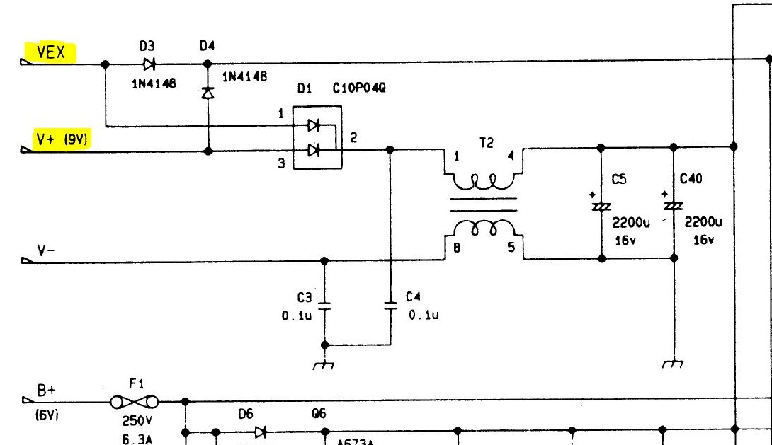
NOTE: If the +/-12v and -5v rails will be required on the ISA Bus, these will need to be provided externally, more on that later.
PCB Parts List
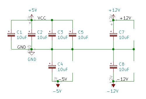
| Designator | Description | | ISA1, ISA2 | ISA 8bit edge connectors - 62-pins (2x31) | | J1 | DIN 41612 96 way connector (TE Connectivity 5650461-4) | | C1, C2, C3, C4, C5 | 16v 22uF Electrolytic 2.5mm pin pitch | | C7, C8 | 25v 22uF Electrolytic 2.5mm pin pitch | | External Power Connectors (Optional) | | C10 | 25V 220uF Electrolytic 2.5mm pin pitch | | J10 | 2-pin 5.08mm terminal block | | J7 | 6-pin 5.08mm terminal block | | J8 | 6-pin 2.54mm Header | | Not Installed | | J2,J3,J4,J5,J6 | Various 1.27mm headers (test points only) |
NOTE: The capacitors are used for various power rails, as per the above parts list some can be omitted if you don’t have a need for all the power rails.
Assembling the PCB
I had the PCB made by JLC PCB like the previous board. Once again, a great finish in blue.
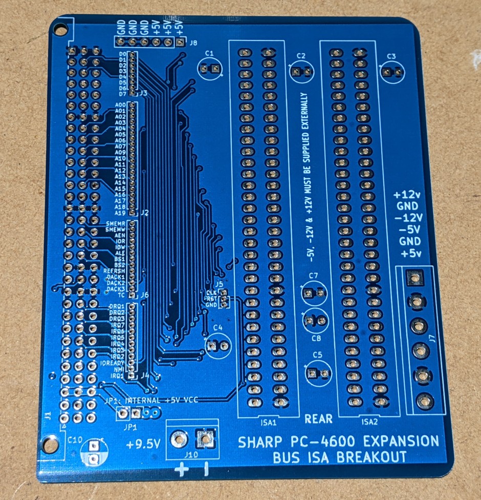
Start by installing the jumper link JP1. This allows the system to provide 5V power to the card. Without this no power to the card will be supplied. It could be removed if an external power supply is used (not tested).
Continue with the all the capacitors.
The 96 pin DIN 41612 connector should then be installed. Be sure to check for any solder bridges once installed. If you wish, insert a suitable screw through the mount holes.
Finally install the 62 pin ISA card edge connectors.
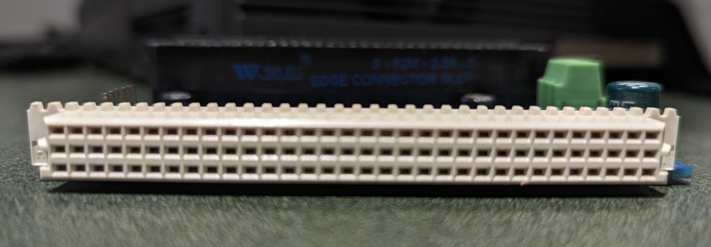
Optionally install the terminal blocks and headers if you are using this option.
This is the finished board with all capacitors and all headers except the 1.27mm installed.
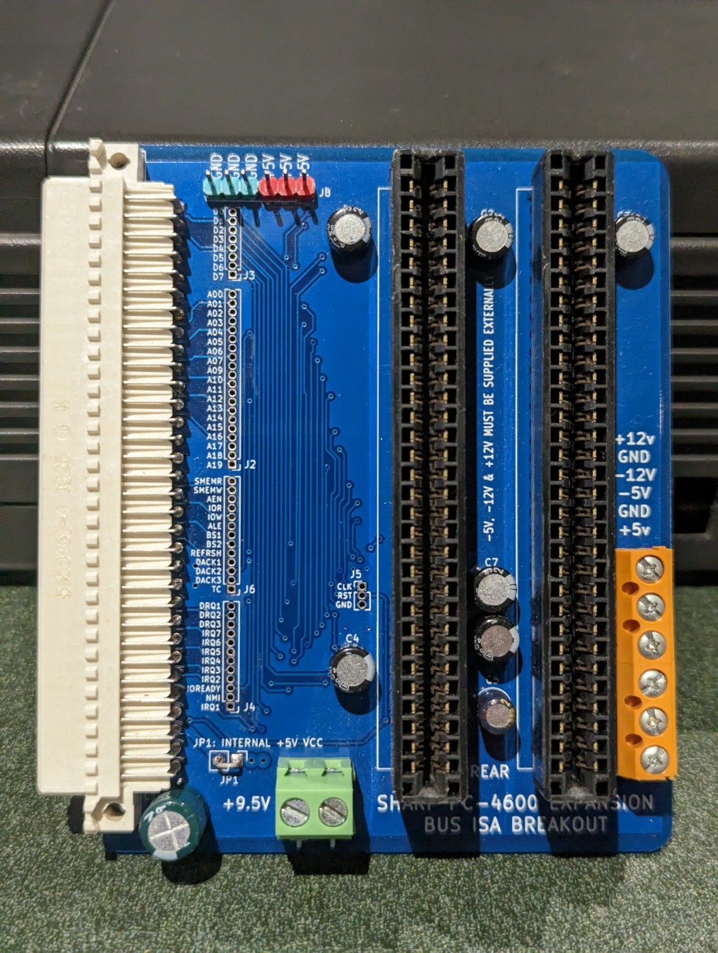
Assembly finished, time to perform some testing.
Installation
Ensure the cover for the Expansion bus has been cut away - use a small set of side cutters to gently remove the plastic cover.
With the system turned off and unplugged from power plug in the Expansion bus breakout card. It should push in firmly, but it won’t click or provide any feedback once connected, use your own judgement. It should look a bit like this.
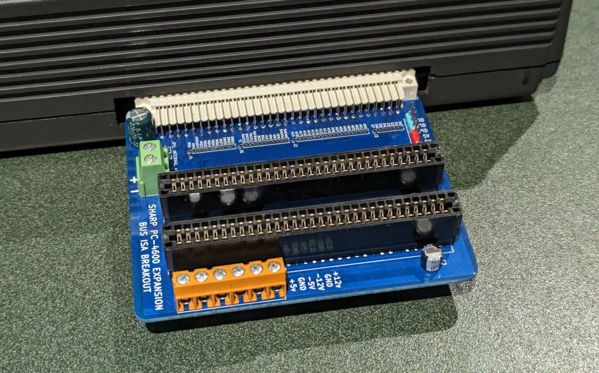
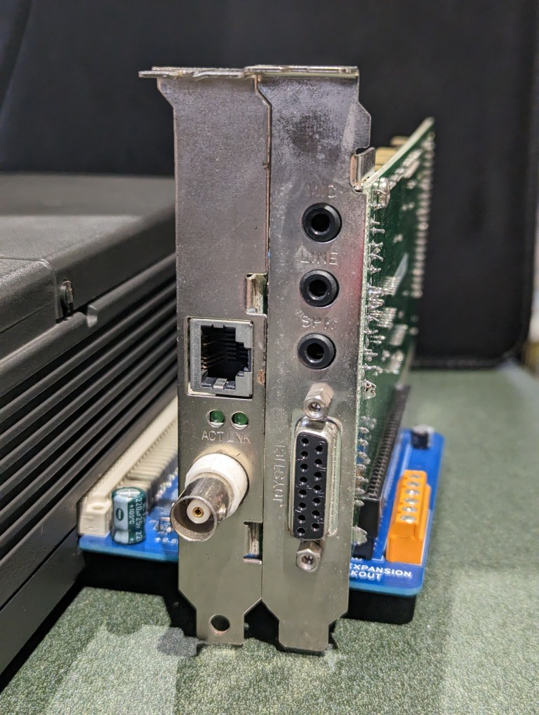
Once you have the card installed, plug in your ISA Cards you wish to use. I have personally used a 10Mbps NIC (RTL8019) and a sound card (ESS1868) that work well with the system, but other ISA cards like an XT-IDE, Video cards, etc… should work fine as well, so long as any BIOS or memory address allocations don’t overlap.
NOTE: On the PCB the rear of the card is marked between the ISA Slots. This can be seen near C5/J10.
I do know that BIOS memory addresses do get scanned by the inbuilt bios, I don’t have a list of the addresses it scans though, so your luck may vary.
Summary
This breakout board provides a much-needed expansion for this system to be incredibly flexible.
When using this card, please be aware of the following
WARNING: I accept no liability for any damage caused. This card is not an official product and with the limited documentation available for the system, there is potential for damage, including power, static electricity, faulty plugin card, etc.. to damage the internal system.
WARNING: Internal power supply parameters are not documented, so be careful what extra power requirements external cards use. I have tested with a sound card and a network card, and the internal PSU seems to handle that OK. YOUR RESULTS MAY VARY
NOTE: Only the 5V rail is passed out from the system. If the expansion cards need +/-12v or -5v, these will need to be supplied from an external supply.
NOTE: If using an external power supply, you may need to ensure the sequencing of the rails are correct. Normally the cards and system would be used to all rails coming up at the same time. An external power supply may need to be triggered by the built in 5v power to ensure all rails are maintained and removed at the same time with the system power.
Files
The below files were used in making this project, you can use them freely for personal, non commercial use.
